Sunday, November 6, 2011

more pictures

Things are looking good! I installed the Evnetics TPS and the Netgain speed sensor, and rewired the vacuum pump to be on a relay. All went well, I went for a 10 mile or so test drive and had no cutouts or faults. I did lots of experimenting with settings, I’ve settled (at least for now) on 400a battery side and 750a motor side. I’ll just rely on my judgement and right foot control to keep from spinning tires or breaking CV joints… Anyway, with only 400a from the battery I’m not able to get 750a for long at all off the line, but it starts high, then holds over 600a for a while (up to about 2000rpm or so). With these settings it’s pretty quick off the line, and certainly fast enough for daily driving with a little fun when desired. I will still hit a low voltage alarm on the MiniBMS if I try to sustain more than 300ish amps for too long, so I set the low voltage ‘soft’ limit to 135 volts in the Synkromotive software. This lets me use up to 400a briefly, and the controller will taper it back for me when needed. It seems to work well, I did some intentionally hard pulls and never heard the alarm after setting this limit. I never felt any kind of cutback, the controller handles it smoothly. I’ll have to go back to my test road soon and re-test the 0-60.

here's a bunch of photo's from the weekend:

the old potbox
From 2011-11-06 synkro

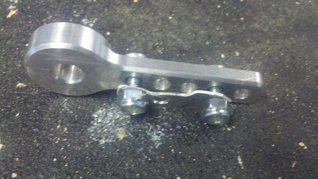
the custom cable holder. just a simple piece of sheetmetal bent and drilled to hold the nub on the end of the cable. the holes in the TPS bracket are already the perfect size for this, so the cable is sandwiched between the arm and this little bracket. each side holds the nub, and it's free to rotate. simple and effective.
From 2011-11-06 synkro

here is the arm with the cable attached
From 2011-11-06 synkro

here's the whole throttle assembly attached. it is truly a piece of beauty! I'm not sure my car is worthy of such a nice part. it certainly deserves a nicer mounting bracket...
From 2011-11-06 synkro

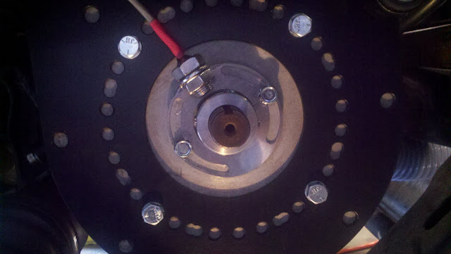
here is the Netgain speed sensor. Very easy to install, the only challenging part was that my motor endshaft had just enough surface rust on it to keep the collar from sliding on. i had to remove the wheel to get better access, then lightly sand the shaft with some 600 grit paper to smooth it up enough to install the collar. although looking at this photo, i can see that I accidentally lined up one of the set screws with the keyway. dang, I'll have to get back in there and rotate it a bit.
From 2011-11-06 synkro

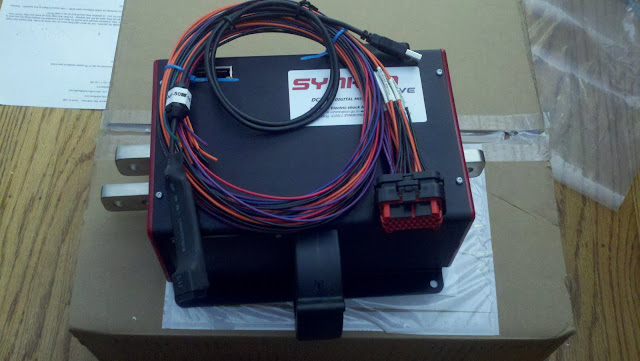
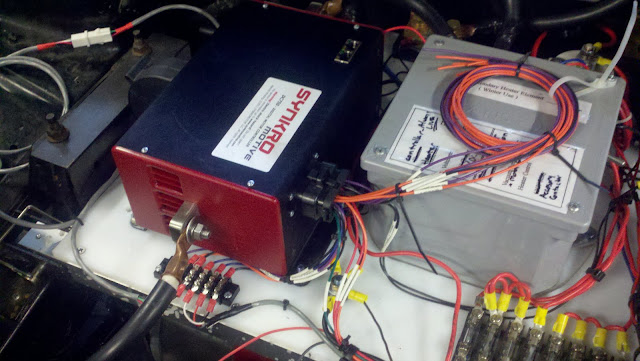
here's the controller! the small terminal block right in front of it holds the connections to the speed sensor and the throttle. The bundle of wires on my heater controls box are the extra wires not needed for my installation (reversing contactor controls, various outputs, etc). Not sure what to do with those yet... all the wires plug into the controller with a nice waterproof connector, which seems a little odd since the controller itself is obviously not waterproof. Anyway, the wires were all nice and long, easy to route and connect up.
From 2011-11-06 synkro

here's the backside. Yes, I'm using a second EV200 contactor for my high voltage accessories. Yes, it's overkill.
From 2011-11-06 synkro

and the overall shot. this is pretty much finished up. You can see the 12v relay next to the terminal strips, that's for the vacuum pump. The loose wires heading down in the front of the photo are going to the motor blower. I still need to clean up and re-route those wires.
From 2011-11-06 synkro

That's it for now. Hopefully it will stay this way for a little while. I do need to put on some of the plastic bits back on up front to get it ready for the rain, but it's basically ready to be my daily driver now.

Friday, November 4, 2011

Synkromotive installed

From 2011-11-04 controller

I was supposed to spend the weekend in Tahoe, but it's snowing, cold, and I've been sick for a few weeks. I'm really not up for it right now, so I stayed home. On the bright side, I spent some quality time in the garage and got the Synkromotive controller installed tonight! Pretty straightforward, the hardest part was actually getting to the reverse light wire. I had to pull out the 12v battery, and battery tray to get down to it.

All the existing high voltage cables worked as is, I really didn't have to move much around at all One motor cable is now on the opposite side of the controller, but the cable length still works fine. It's just routed differently. The controller comes with all the wires pre-attached to a connector, it took a while to sort them all out and figure out what went where, and which ones I don't need. The ones I'm not using I just zip tied out of the way. Not sure what I'll do with them long term, I don't really want to cut them off permanently. The ones I do need, I just went one at a time, and took my time connecting them where they need to go.

Anyway, I don't have the new throttle position sensor yet, so I just wired in the existing two wire potbox that's in the car. Not ideal, but it will work.

With the main pack disconnected, I powered up the controller and hooked it up to a laptop with the Synkro software installed on it. It just plugs into a USB port, the program recognized the controller when it opened up and everything looked alright. The interface is sweet, just simple and easy to use. I set the battery parameters then calibrated the pot box. So far so good! I flipped on the main pack breaker, and went for the full test. Car in neutral, one hand turning on the key, and the other holding the cord to trip the breaker. Key on, the controller's fan hummed for a few seconds then went off. The stats on the computer showed pack voltage was on. I gave it a little throttle, and there was a nice little hum as the motor slowly turned over.

After verifying everything for a little bit, I took it for a test drive. For the initial test I set the battery amps to 300, and the motor also to 300. first thing I notice is that it is SMOOOOTH!!!! Finally, I can drive it like an electric car. After a few blocks, I pulled over and bumped the motor amps up to 500 (battery still at 300). Nice! Much quicker off the line. Drove around like this a while, then decided to really go for it and bump it up to 750a. Just on the motor side, battery was still at 300. Very nice! Spun the wheels a bit in second gear. Definately faster now. In the interest of not doing anything stupid, I called it a night and came back home.

Up and into the driveway (up a hill while turning and transitioning over a driveway, it's been my nemesis for driving smoothly) without drama, I could stop and start at will. I'm liking it already! And this is with the old potbox, should get even better with the new TPS.

Thursday, November 3, 2011

charger wiring

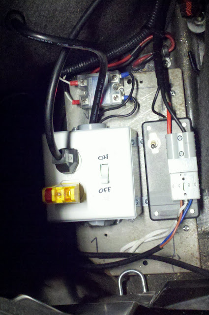
I did a little charger wiring clean up today. Nothing new functionally, just a little cleaner and easier to use. In the picture you can see the power inlet cord coming through the side from the gas tank door (upper left of the picture), one leg goes through the solid state relay controlled by the MiniBMS, then it goes into a junction box with a dual pole switch leading to an outlet. This is so I can plug the extension cord into the car without the charger being 'live' yet so I don't get arcing at the extension cord. The charger plugs into the outlet. From the charger, I then mounted the Anderson connector to a small project box that has a simple 20a rated switch with one leg of the charger output going through it. This is so I can power on the charger with the output disconnected, then just flip the switch instead of having to plug in the Anderson every time.

So, the process goes like this.
1) make sure both switches are off.
2) plug in cord to car.
3) flip switch on junction box to power charger.
4) flip switch on small box to connect output to battery pack.
From 2011-11-03 plug

Wednesday, November 2, 2011

sloooow charger

so I drove 46 miles yesterday. Several trips throughout the day, mostly 35ish mph, some freeway. I plugged in last night, it was not charged yet this morning when I went to take the kids to school! It was probably close to 12 hours on the charger at 5.8a... guess I need to plug in earlier (or get a bigger charger...). Bummer since the charger screws with my radio reception in the house.

Friday, October 28, 2011

new controller

look what just showed up on my doorstep!
From 2011-10-28 synkro

It's my new Synkromotive controller. bummer I won't have a chance to install it for a while...

Monday, October 24, 2011

alarming

I blipped the low voltage alarm on the MiniBMS this morning (the MiniBMS is an individual battery monitoring system. Each cell has a circuit board on it and they are all connected together to a master board that keeps track of their voltages and reports any problems). I was accelerating onto the freeway in third gear. Basically it was a full throttle 0-60 run in 3rd gear trying to get up to speed of traffic, so probably 15 seconds at least at max throttle. I heard the alarm for just a second as I approached 60mph while pulling 300a from the batteries (48x 130ah cells). According to the numbers I can find online for my tranny and final drive ratio, 60mph in third gear is 5000rpm, so it's right up there on the high end of where I should be taking the motor. Anyway, I heard the alarm beep for just a second just as I was going to make the shift to 4th gear anyway. I was showing about 130v (153v nominal system), though it's a small analog gauge and a bit hard to read while driving (+/- 10 volts would be hard to tell).

Anyway, I should be able to pull many more amps than that without this much voltage sag, not going to worry about it quite yet, but it's something to wonder about. Hopefully it's something simple like needing bigger wiring or better connections in the battery loop. I do know that right now a few of my cables are 2awg which is awfully small. They should all be 2/0, and will be eventually once I decide exactly how I want all the batteries laid out and tied down.

Sunday, October 23, 2011

motor mounts

Finished up the motor end torque mount today! I think it's pretty good, you can also see the finished upper mount in these photo's,,,
From 2011-10-23 mount

From 2011-10-23 mount

From 2011-10-23 mount

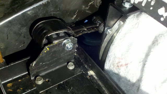
I used another stock Saturn transmission torque strut just to keep it simple. I was originally wanting to attach it to the frame on the other side of the torque strut with some type of flat plate with a bolt welded onto it, but this was easier and there's plenty of room. Plus I had this welded piece of angle already lying around, it is the old upper motor mount I replaced earlier. It's bolted down directly to the battery rack which is VERY solidly welded to the frame. No strength worries there. There's still enough room on the battery rack for 12 cells when I move them up out of the trunk. I still have to remove the bracket to clean it up a little and paint it, but I needed to get the car running for the week. I'll paint it later.

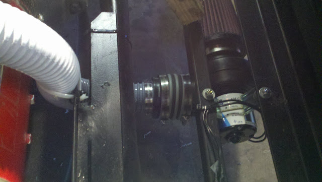
here's a few shots of the motor blower and hose routing. The blower is rubber mounted to the underside of the front battery racks.
From 2011-10-23 mount